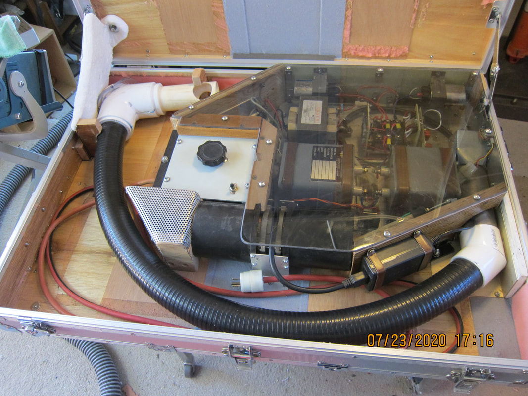
My intent with this unit is to display every component, every connection, and all precautionary measures taken. My hope is, makers will be able to duplicate these. Stored energy in this system is low (about one tenth of that seen in clinical TMS systems). Is this enough?
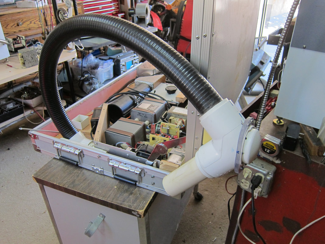
Applicator Coil Assembly
I chose a heavy-duty PVC flex hose to minimize stresses incurred on the internal coaxial cable. The weak point in this design is the applicator coil cover. Spares are readily available, in case of breakage.
TMS System #5: Schematics, Parts List, Test Data, Wave Forms, Procedures
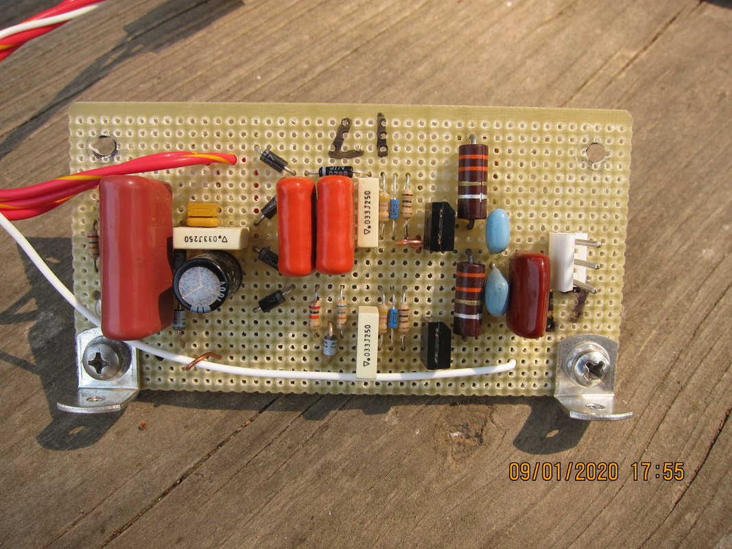
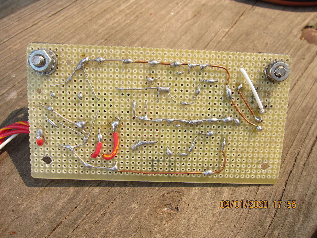
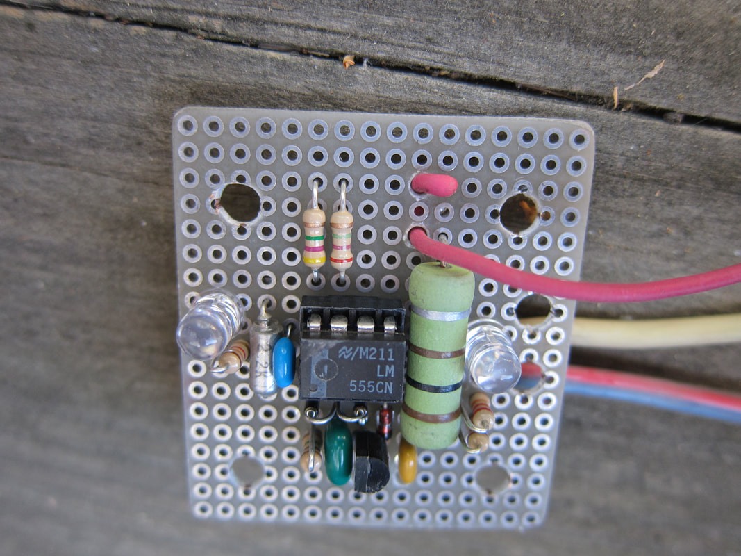
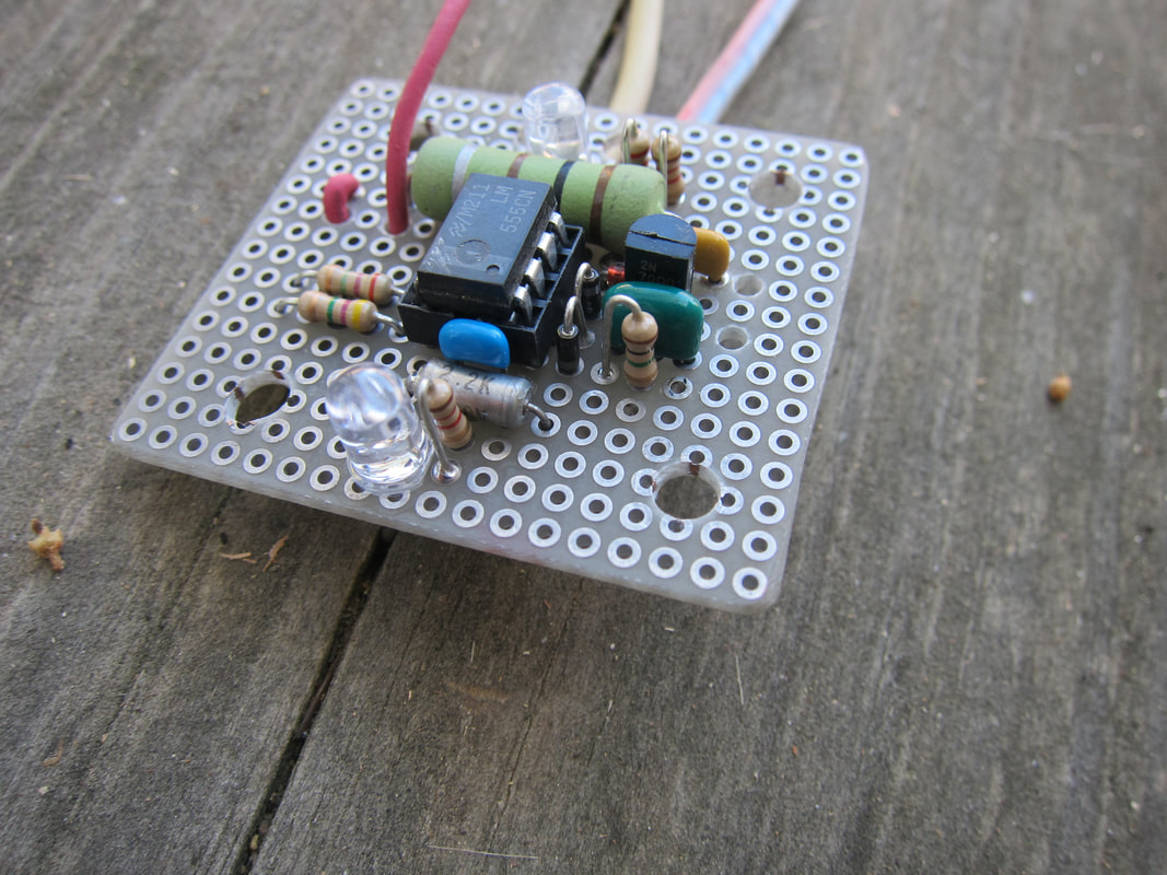
Pulse Driver Board
|
|
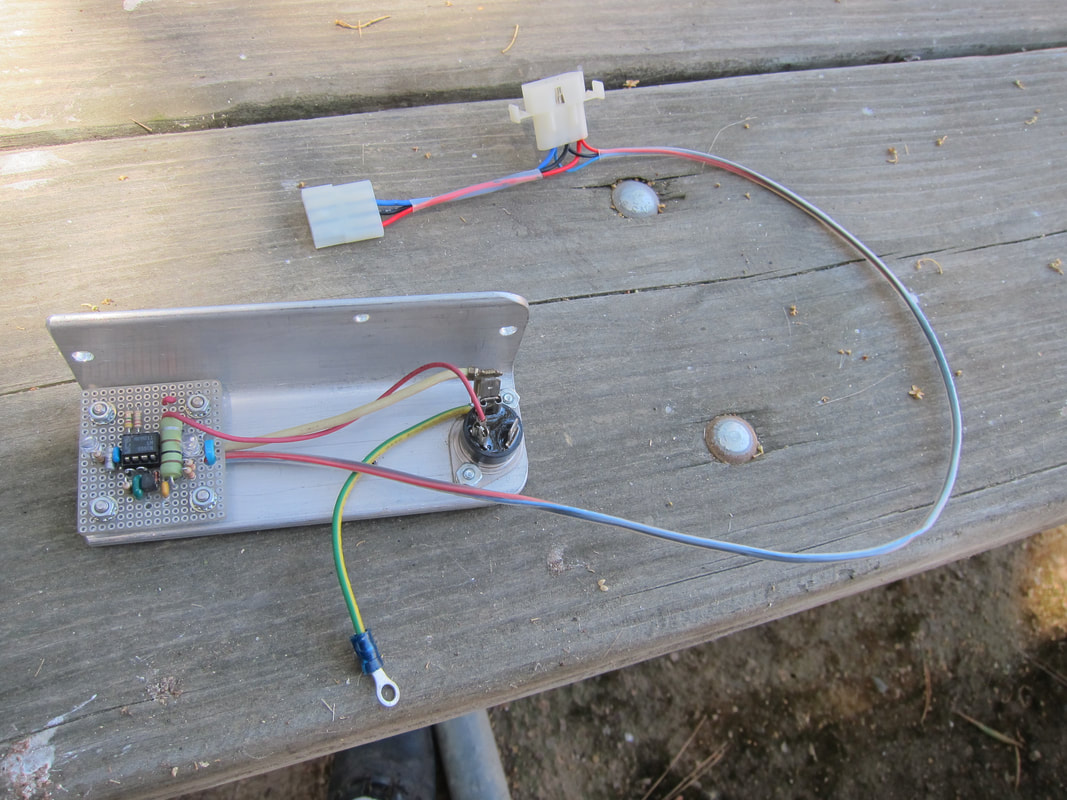
Power Control, Cycle Timer
|
|
|
|
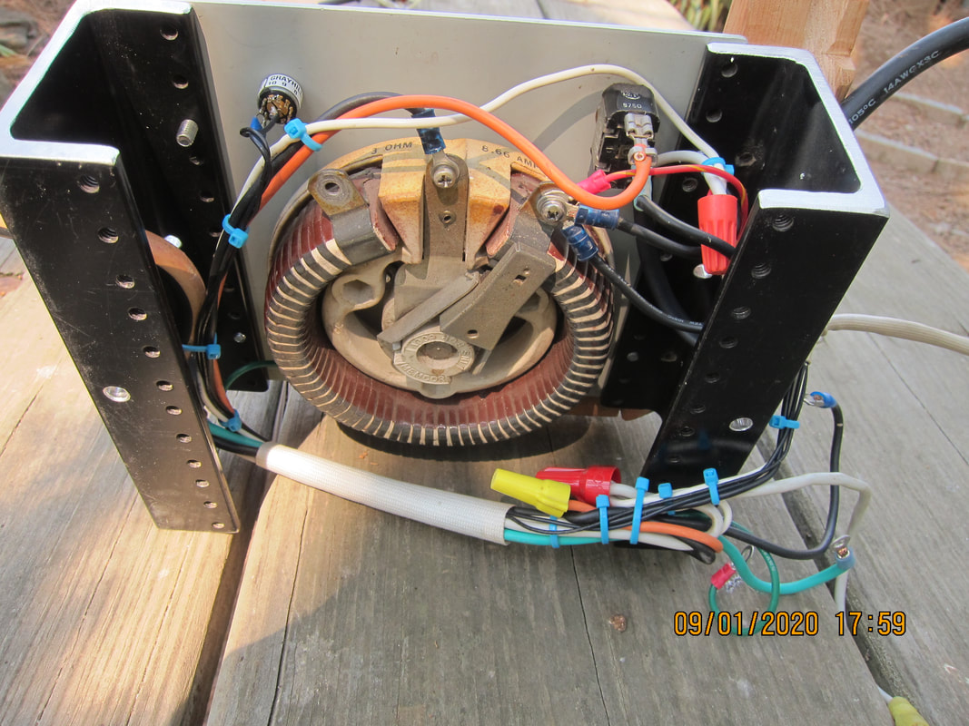
Raw Supply, Switch Deck
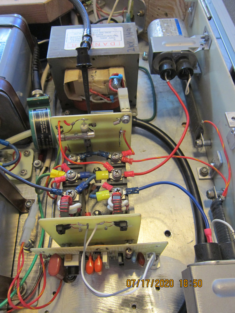
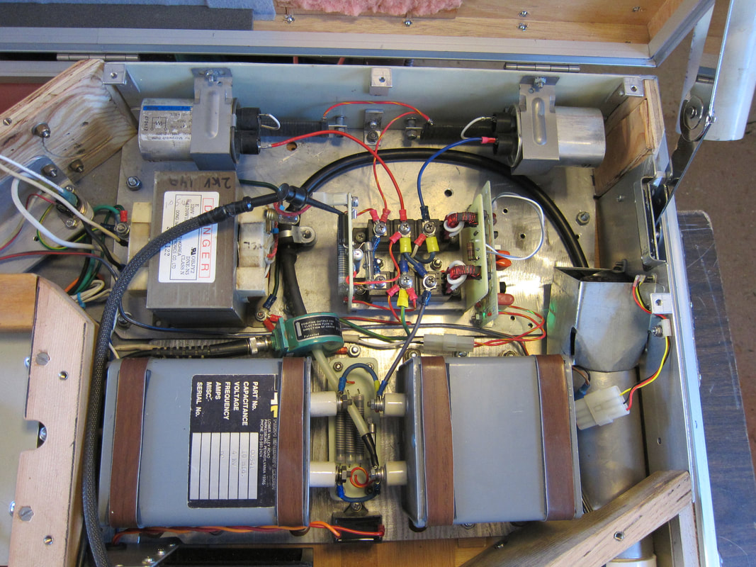
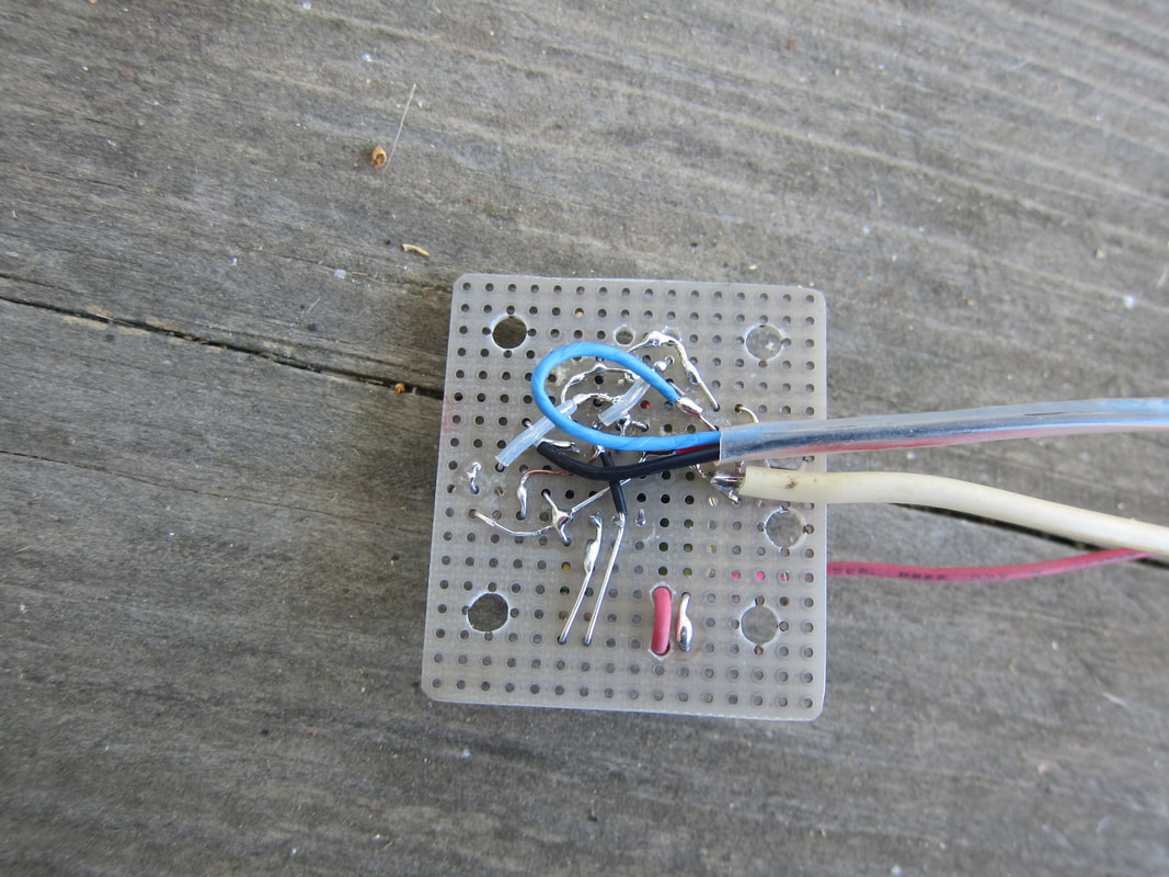
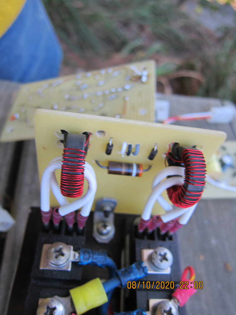
Gate Drive
|
To the right, you will notice fiberglass-silicone sleeving covering the gate drive wires. Notice also that there is air spacing surrounding the gate drive wires. High voltage AC is present here, and this tends to degrade insulation of any form. 2500 volts AC hardly ever arcs through air, especially given this spacing. But we should treat our AC wires like they are bare conductors, and give them ample spacing to prevent arcing without insulation. Then the added insulation gives another layer of protection, but only if the insulation doesn't come into physical contact with opposite-polarity conductors. Given two layers; Teflon and Fiberglass-Silicone insulation, dielectric breakdown would appear unlikely, even if the lines were to touch.
|
|
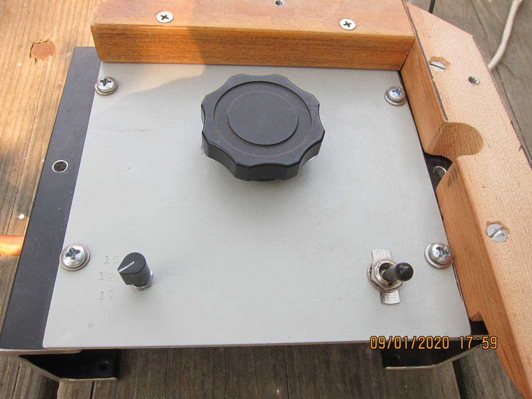
Front Panel
|
Power level control isn't really necessary. Applicator coil spacing could just as well reduce apparent pulse energy. Thyristor style phase-control might be applied later, but rheostat control is simple. Increased source impedance is desirable for capacitor charging when reduced power levels are found acceptable. My objective was to develop parts of this circuit which others would find difficult. Primary power control ranks low in priority for me, as well-known methods are available for achieving this.
|
|
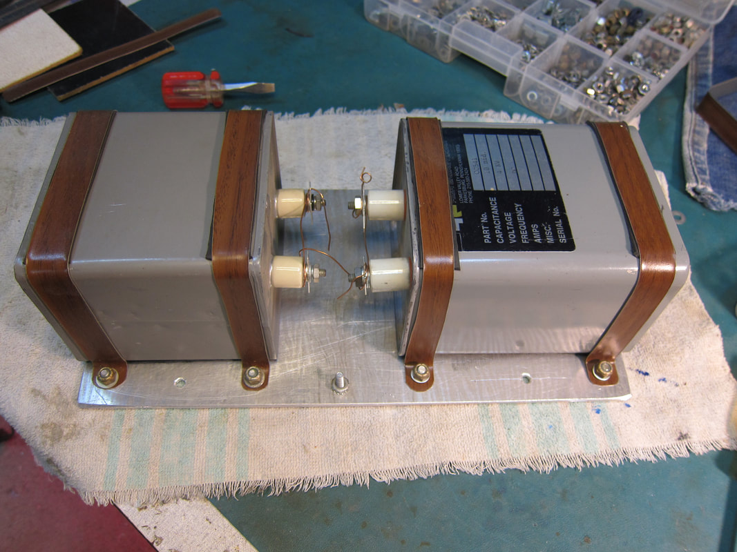
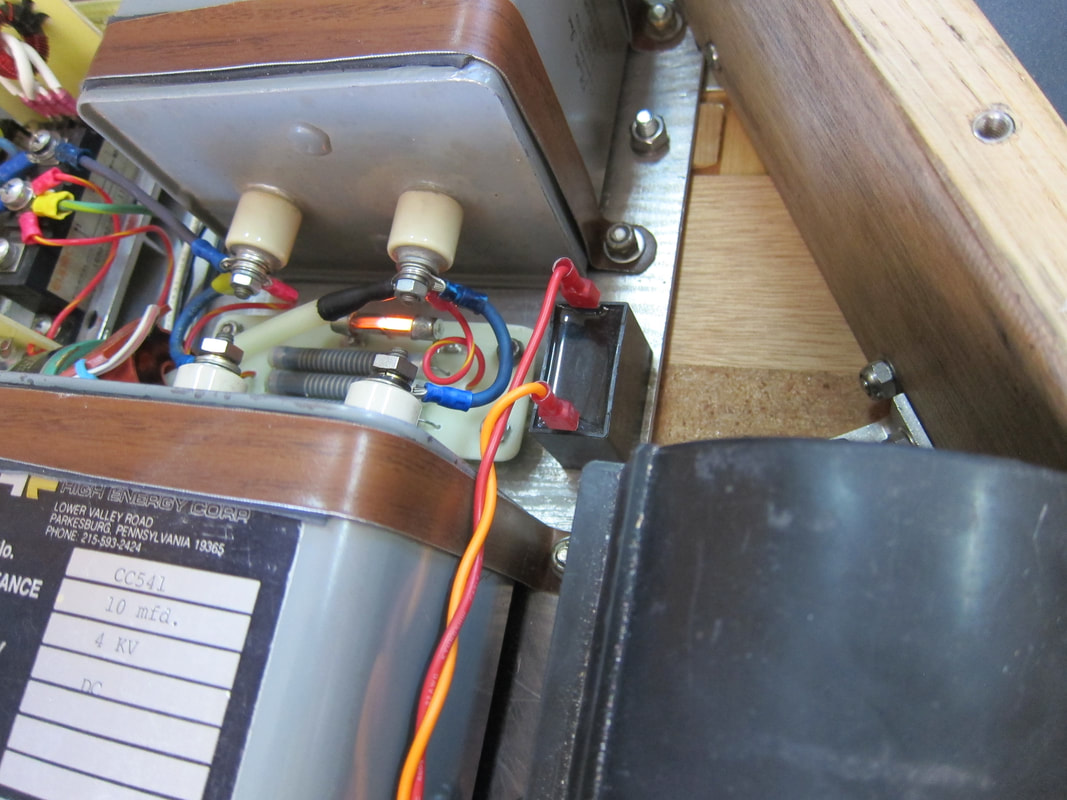
Cap Bank
|
|

Simple TMS Design by Jeffrey Reagan is licensed under a Creative Commons Attribution 4.0 International License.
Based on a work at https://www.photonics.com/Article.aspx?AID=53525.
Clients we love