In this circuit, we ground both ends of the SCR stack. Only the center point floats at high voltage potential. This simplifies mechanical construction. 6-32 screws protrude inward from the center of each heatsink to locate the hockey puck SCRs. The center plate has a 6-32 threaded hole in the center, with a set screw inserted. This locates the center plate in the assembly process. Channel material is aluminum, taken from a server rack. Faces are sanded flat on a belt sander and given a chromate flash, to prevent oxidation.
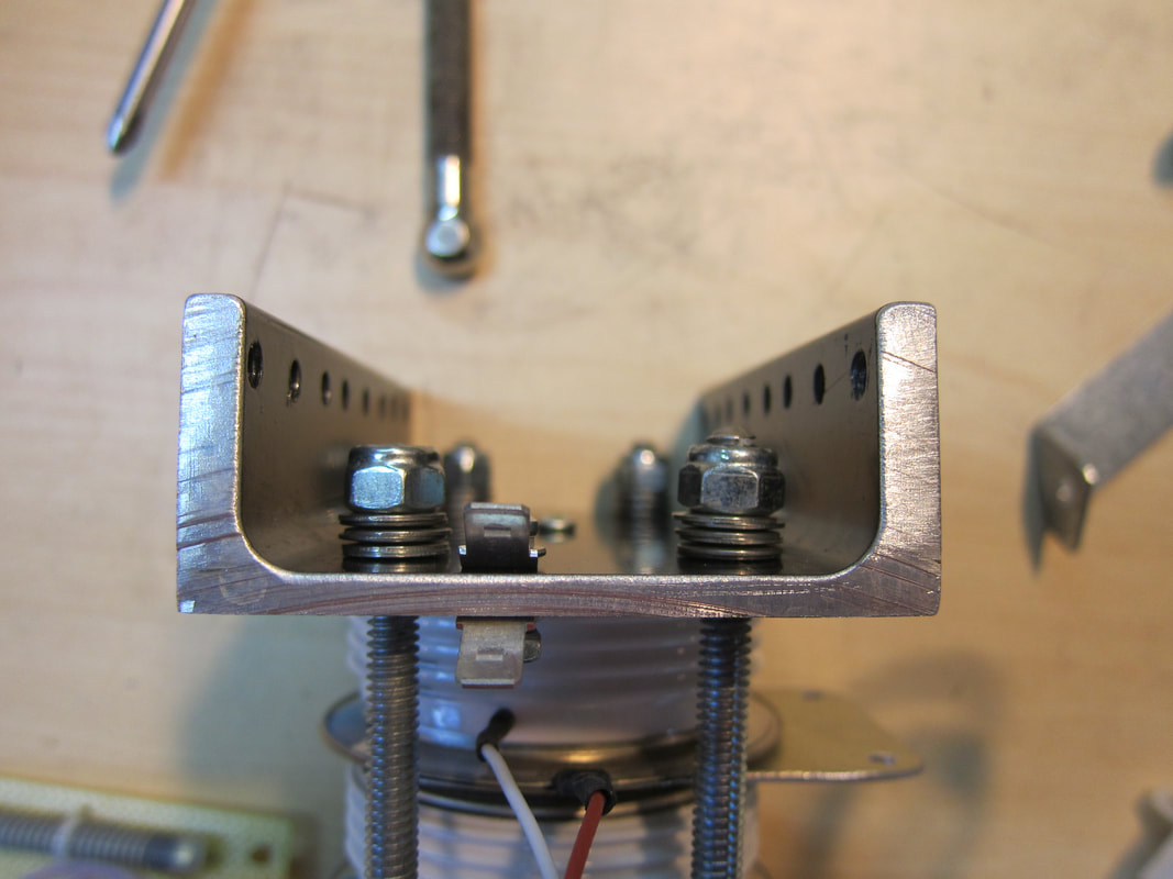
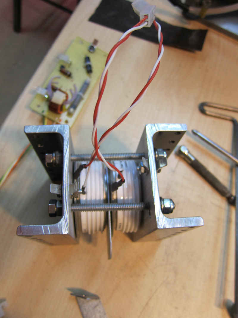
Belleville spring-washers are used to apply clamping force. Notice they are not completely crushed. This accommodates SCR thermal expansion. (The SCRs don't get hot.) Nylon locking hardware allows tension to be set such that force will be maintained. Dual-nuts are used on the opposite end of each 1/4"-20 stud, locked together to prevent loosening of hardware from vibration.
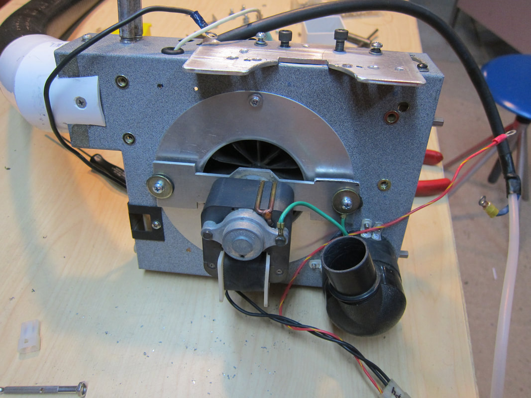
Notice the black ABS 90-degree elbow, which blows air at the center of the SCR stack. Gate drive wires are positioned away from each other, which isn't obvious from this viewing angle.
Here we see the applicator coil umbilical connected to the blower box.
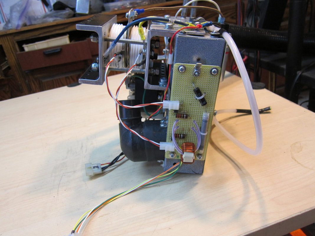
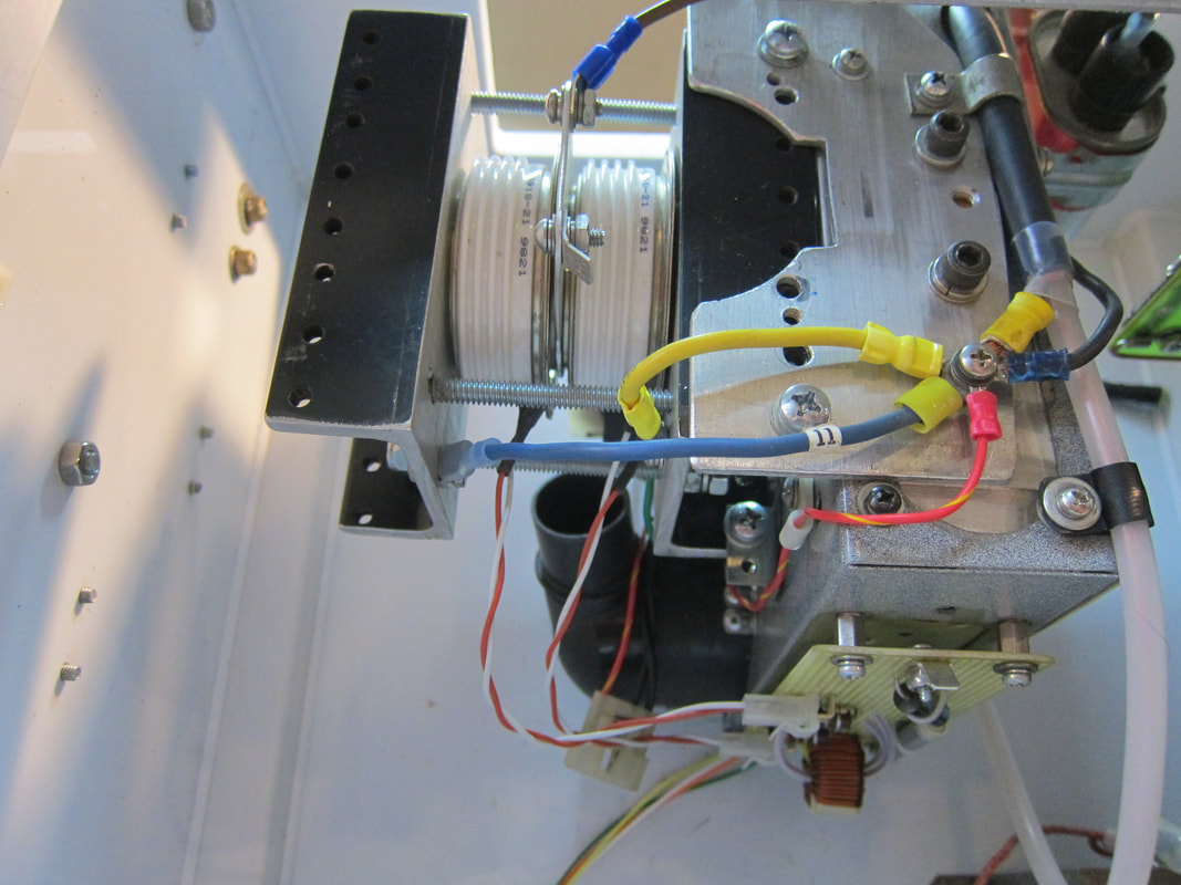
Air spacing between gate-drive leads is more obvious viewed from this angle. The electrical tie-point seen to the right is the single-point-ground for the discharge path. This unit has a plastic chassis, so we cannot count on chassis continuity to reference everything together. Two parallel wires reference the Switch Deck chassis to the line-cord ground, also providing an AC return-path to the High Voltage Transformer secondary: one runs via the Fan Power Connector (via JP4, to the red and yellow wire); the other is a green wire going to the Gate Drive Board (via connector JP5, and then to the ground-referenced primary-SCR via a red SCR Cathode lead, seen here twisted with a white gate lead). I never rely on mounting hardware for electrical continuity: I run wires wherever current will flow. All #16 Gauge Teflon insulated wires are soldered into respective Molex pins. Repeated crimp failures were seen (which released wires), necessitating soldering.
Snubber capacitor is shown above, 10 Ohm snubber resistor is shown below.
SCRs used here are obsolete. Any similar type should work. Digikey lists these: IXYS: N1725MC320 and Powerex: C702CB. I courted a source on Alibaba who quoted me prices of just over $100 bucks apiece for a Powerex equivalent for those used here.
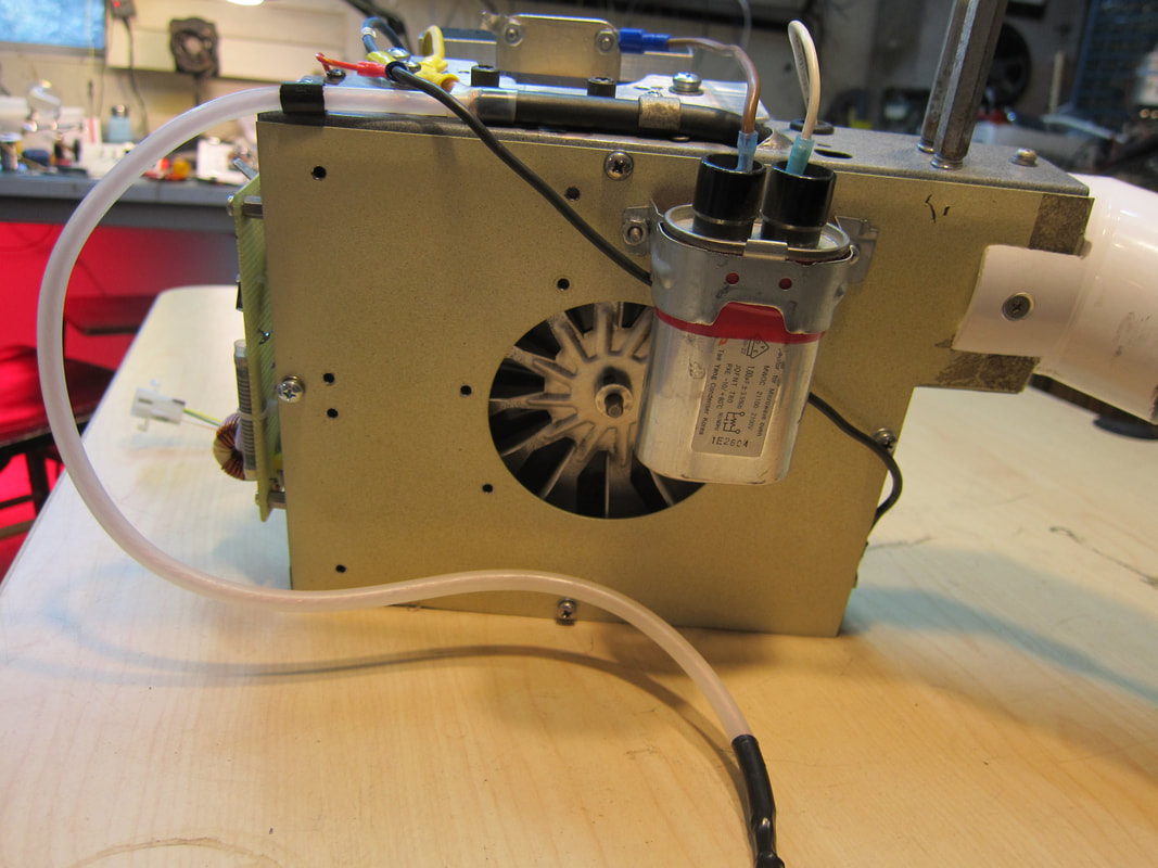
This blower box was adapted from a beauty-salon stationary hair dryer. Power dissipation could be 88 Watts if pulsing was running continuously. Actual duty cycle under normal operation is lower, so power dissipation should be closer to 24 Watts.
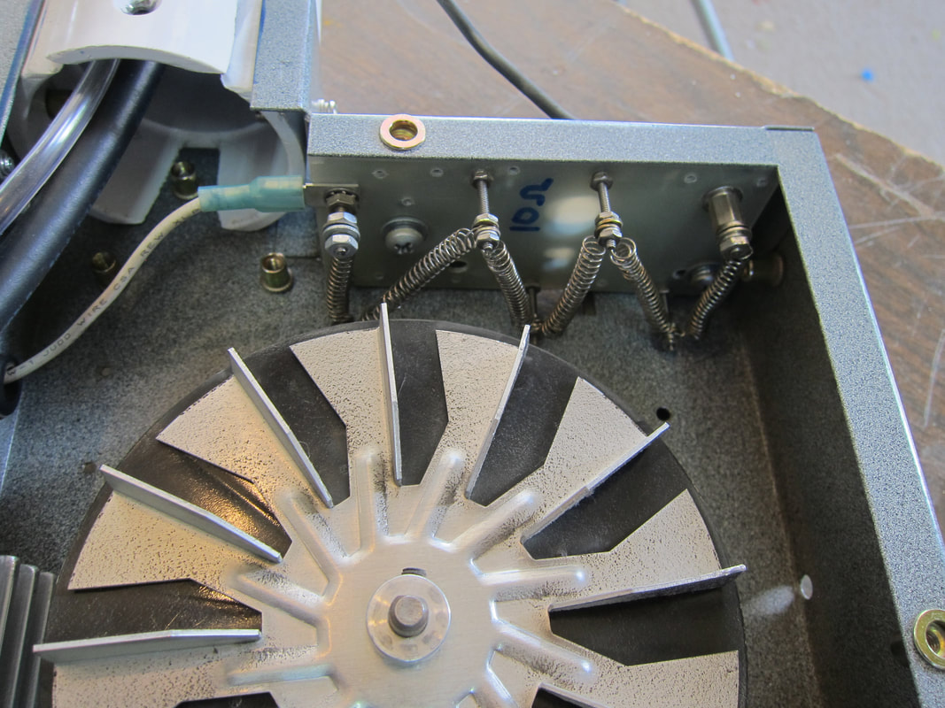
The 10 Ohm snubbing resistor seen here is constructed from a piece of nichrome wire removed from a hand held hair dryer heating element. Snubbing circuitry was installed when smaller SCRs were in the circuit. In the prior case, SCR recovery-time showed a rather abrupt turnoff, so peak reverse voltage skyrocketed. These hockey puck SCRs may show a slower turnoff transition, thus eliminating the need for snubbing components. More research will determine if snubbing can be omitted. Future systems should have an airflow switch, to shut the system down in the event of fan failure. I lubricated these motor bushings prior to reassembly.
This blower box was adapted from a beauty-salon stationary hair dryer. Power dissipation could be 88 Watts if pulsing was running continuously. Actual duty cycle under normal operation is lower, so power dissipation should be closer to 24 Watts.
The 10 Ohm snubbing resistor seen here is constructed from a piece of nichrome wire removed from a hand held hair dryer heating element. Snubbing circuitry was installed when smaller SCRs were in the circuit. In the prior case, SCR recovery-time showed a rather abrupt turnoff, so peak reverse voltage skyrocketed. These hockey puck SCRs may show a slower turnoff transition, thus eliminating the need for snubbing components. More research will determine if snubbing can be omitted. Future systems should have an airflow switch, to shut the system down in the event of fan failure. I lubricated these motor bushings prior to reassembly.

TMS Design by Jeffrey Philip Reagan is licensed under a Creative Commons Attribution-ShareAlike 4.0 International License.
