Primary Power Distribution:
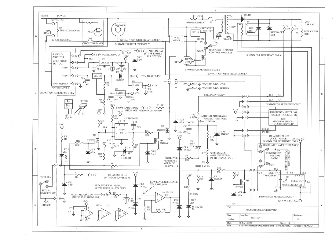
Incoming 120 Volts energizes the Pulse Driver Board immediately. Closing the circuit breaker powers up the fan, the Triac-Driver Power Supply, the logic power supply, and the Zero Crossing Detector circuit (which isn't used in the present design). A Triac activates the high voltage (HV) transformer, as commanded by the Arduino Uno controller (or by a LM555 burn-in timer). In the Fixed Frequency Mode (labeled MAX on the small front panel), the pulse driver produces continuous 15 Hertz drive for the output SCRs. This dissipates stored energy in the capacitor quickly after each pulse train (for safety reasons). In the Normal Mode HV capacitors will stay charged long after power fails. A neon bulb on the HV capacitor bank indicates presence of lingering high voltage.
Prompt Normal-mode capacitor discharge was desired. To achieve this, deactivation of the circuit breaker enables the Pulse Driver circuitry, thus dissipating stored energy quickly. Pulse generation is activated through an extra set of contacts on the Max/Normal mode switch. In the Max mode, Pulse Enable receives 120 Volts directly. In the Normal mode, Pulse Enable receives 120 Volts through a deactivated blower motor winding.
High voltage section primary line current is adjusted using the Memcor 3 Ohm rheostat. One peculiarity of this design: half-wave rectified Capacitor input filtering draws high peak line current (sometimes exceeding 40 Amps peak). Average line current may reach 12 Amps. A 15 Amp fuse protects the HV transformer.
High Voltage On Command, normal operation:
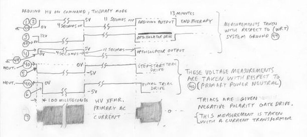
Looking at the schematic above, Arduino HV-ON Command output (D1) enters the picture at the middle left at test point TP-1. (Setup Mode will be discussed separately.) This signal passes to TP-2 unaffected, then two inversions occur, first at the 2N7000 FET (TP-3), then again at the HCPL2601 optoisolator (TP-4). Whenever Arduino output D1 goes high, both triacs are driven into conduction by 2N7000 FETs. The first FET applies negative gate drive right away (to TP-5) to the first Triac, which begins applying power softly via a 10 Ohm Step-Start resistor. After a short delay (~100 milliseconds), the second 2N7000 FET activates, applying negative gate drive (to TP-6), thus driving the Final triac into conduction, applying full power to the HV transformer. When Arduino-output D1 goes low, both FETs deactivate their respective Triacs quickly. Approximate waveforms are shown below.
The High Voltage ON command gets interrupted after the first delivered pulse in the setup mode (regulated single-shot mode). This will be discussed in greater detail later.
Incoming 120 Volts energizes the Pulse Driver Board immediately. Closing the circuit breaker powers up the fan, the Triac-Driver Power Supply, the logic power supply, and the Zero Crossing Detector circuit (which isn't used in the present design). A Triac activates the high voltage (HV) transformer, as commanded by the Arduino Uno controller (or by a LM555 burn-in timer). In the Fixed Frequency Mode (labeled MAX on the small front panel), the pulse driver produces continuous 15 Hertz drive for the output SCRs. This dissipates stored energy in the capacitor quickly after each pulse train (for safety reasons). In the Normal Mode HV capacitors will stay charged long after power fails. A neon bulb on the HV capacitor bank indicates presence of lingering high voltage.
Prompt Normal-mode capacitor discharge was desired. To achieve this, deactivation of the circuit breaker enables the Pulse Driver circuitry, thus dissipating stored energy quickly. Pulse generation is activated through an extra set of contacts on the Max/Normal mode switch. In the Max mode, Pulse Enable receives 120 Volts directly. In the Normal mode, Pulse Enable receives 120 Volts through a deactivated blower motor winding.
High voltage section primary line current is adjusted using the Memcor 3 Ohm rheostat. One peculiarity of this design: half-wave rectified Capacitor input filtering draws high peak line current (sometimes exceeding 40 Amps peak). Average line current may reach 12 Amps. A 15 Amp fuse protects the HV transformer.
High Voltage On Command, normal operation:
Looking at the schematic above, Arduino HV-ON Command output (D1) enters the picture at the middle left at test point TP-1. (Setup Mode will be discussed separately.) This signal passes to TP-2 unaffected, then two inversions occur, first at the 2N7000 FET (TP-3), then again at the HCPL2601 optoisolator (TP-4). Whenever Arduino output D1 goes high, both triacs are driven into conduction by 2N7000 FETs. The first FET applies negative gate drive right away (to TP-5) to the first Triac, which begins applying power softly via a 10 Ohm Step-Start resistor. After a short delay (~100 milliseconds), the second 2N7000 FET activates, applying negative gate drive (to TP-6), thus driving the Final triac into conduction, applying full power to the HV transformer. When Arduino-output D1 goes low, both FETs deactivate their respective Triacs quickly. Approximate waveforms are shown below.
The High Voltage ON command gets interrupted after the first delivered pulse in the setup mode (regulated single-shot mode). This will be discussed in greater detail later.
High Voltage Section
Half-wave rectified high voltage transformer output charges a 20 microfarad output capacitor via the ground referenced applicator coil. A 3 Volt winding on the High Voltage transformer drives a 6 Volt incandescent lamp, to give an indication primary power is applied. A 2.2 Meg-Ohm high voltage resistor powers a neon bulb located on the 20 microfarad capacitor bleeder board. Both indicators can be viewed through a peek-hole next to the Arduino Display. The primary SCR fires, applying the charged 20 microfarad capacitor to the applicator coil. Capacitive discharge establishes a magnetic field surrounding the applicator coil. Collapsing magnetic field continues current flow to recharge the 20 microfarad capacitor negatively, in a resonant fashion.
Data taken while running ten pulses per second showed the high voltage capacitor charging to 2100 Volts positive. Primary SCR firing is quickly followed by negative-going capacitor voltage, which reaches -1900 Volts. Negative polarity persists 2 milliseconds (or a little more), which allows the primary SCR time to recover from the conductive state. Then the Ringback SCR fires. Capacitive-discharge establishes a reverse polarity field in the applicator coil. Collapsing field then drives capacitor polarity positive again, by resonant action, returning +1700 Volts. High voltage transformer output goes positive again, and begins recharging the capacitor again, reaching +2100 Volts over the next six power-line cycles.
A snubber network (1 uF/10 Ohms) was added across the SCRs in a previous revision; this may not be necessary here. Previously, smaller brick-type SCRs showed abrupt reverse-recovery-time switching, resulting in over-Voltage spikes, occurring in each direction. The tendency was, forward current charged the capacitor resonantly. At the end of that, the charged capacitor would begin to create reverse polarity field in the applicator coil via reverse-SCR-conduction. That current would end abruptly. Applicator coil field collapse attempted to maintain constant current through the now-non-conductive SCR, resulting in unchecked voltage excursions, which threatened to over-voltage the SCRs in the reverse direction. I hadn't seen these over-Voltage spikes when I was using hockey puck SCRs in my first unit. Upgrading to hockey-puck SCRs here might have eliminated the need for snubbing. Snubber power dissipation is considerable, as the entire energy stored in the snubber capacitor gets dissipated in the snubber resistor with each switching transition. Eliminating the snubber circuit would both boost efficiency and cut parts count.
Two 2.2 Meg-Ohm high voltage resistors are connected directly across the capacitor for a bleeder. Another 2.2 Meg-Ohm resistor is used to sense output frequency, in a circuit discussed separately.
There are sub-optimal aspects to this design.
- Capacitor polarity can swing negative when transformer output goes positive: secondary current will be high for 2 milliseconds.
- Half wave rectification gives poor transformer core utilization.
- When running a burn-in, the High Voltage Transformer runs hot, because peak primary current is high. Microwave Oven transformers are cheap, so they typically do run hot with continuous use.
- Using a circular applicator coil simplifies construction. Figure-8 coils deliver stimulation to a central point. Circular coils have a dead spot in the center, with stimulation concentrated under the coil perimeter.
- Standard FDA Approved Biphasic TMS systems produce slightly different waveforms from this unit: by applying a 100 microsecond positive pulse immediately followed by a 100 microsecond negative pulse. The result is a 5 KiloHertz fundamental frequency--which exceeds normal brainwave firing rate by at least two orders of magnitude. My Biphasic TMS system delays the negative-polarity pulse by 2 milliseconds. Fundamental frequency becomes 500 Hertz, which is still at least one order of magnitude greater than normal brainwaves. Why would this matter? We wish to pump ions through membranes within the brain, intending to fire neurons. This is a mechanical process. How fast can ions move through membranes? Reversing polarity too soon might prevent ion movement. So waiting longer to apply reverse polarity might better assert neuron state change. Or longer delay time might reduce peak power required to trigger neuron firing.

TMS Design by Jeffrey Philip Reagan is licensed under a Creative Commons Attribution-ShareAlike 4.0 International License.
