JEFFREY PHILIP REAGAN'S WEBSITE
Home
Schematics, TMS #5
Applicator Coil, TMS #5
Test Data
Transcranial Magnetic Stimulator Design
System Schematic, SN #3
TMS REV C, Efficient Monophasic
Pulse Regulator Board
Arduino/Shield Board
Frequency Metering Board
Capacitor Bleeder/PRF Sense Divider Board
Switch Deck
Gate Drive/HV Rect./Reg. Divider Board
Applicator Coil
Small Control Panel
Power Control Module Wiring
Triac Driver Board
Pulse Driver Board
About Me
Search
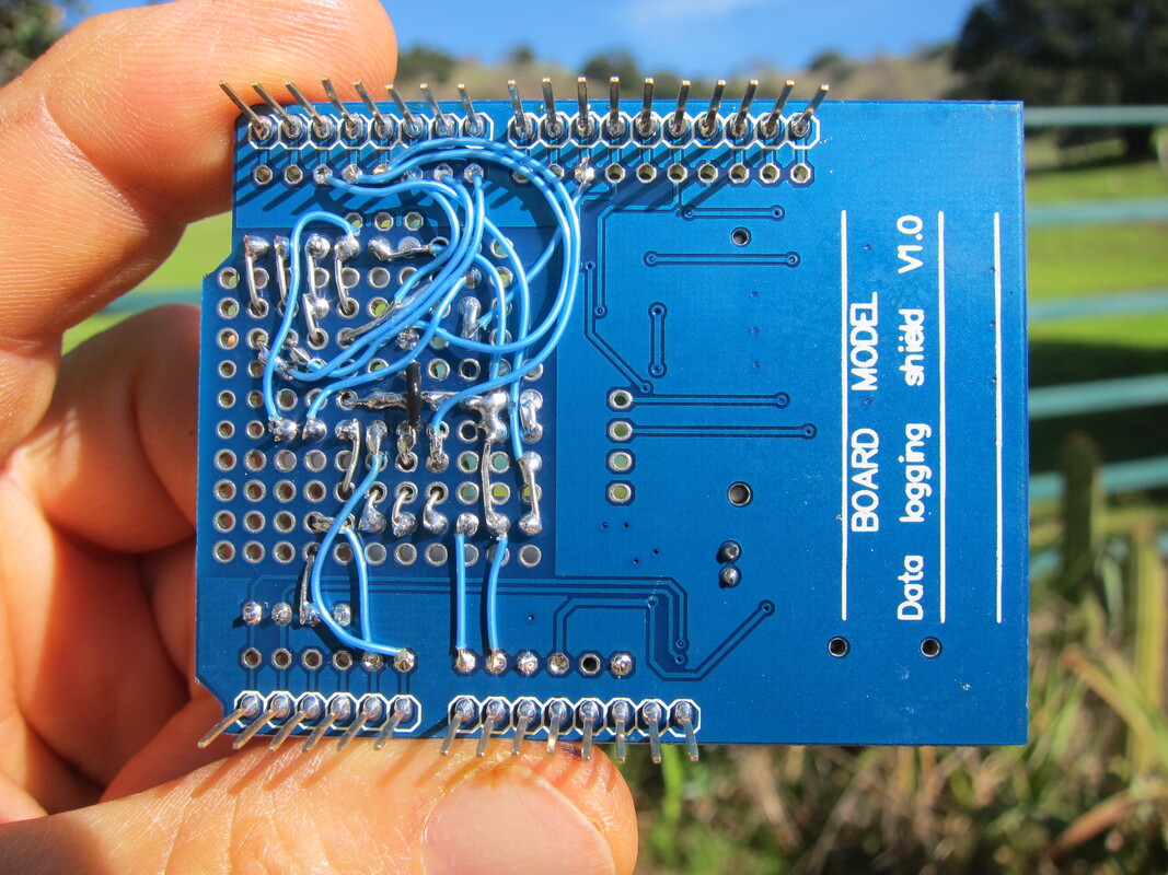
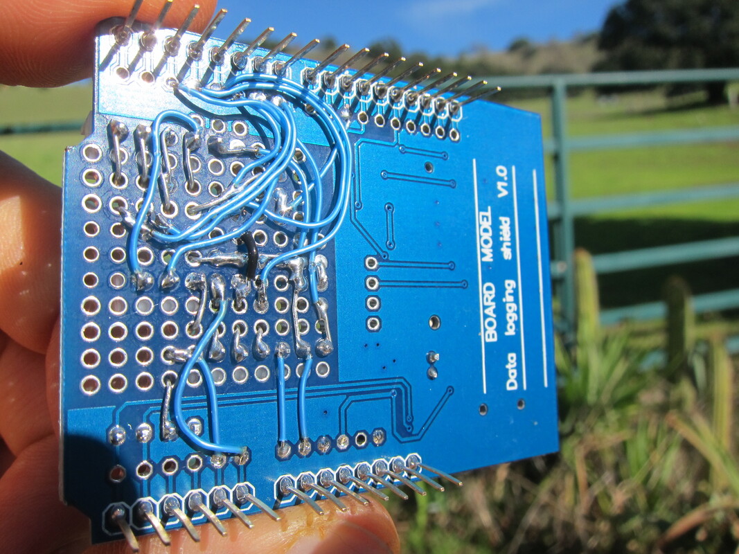
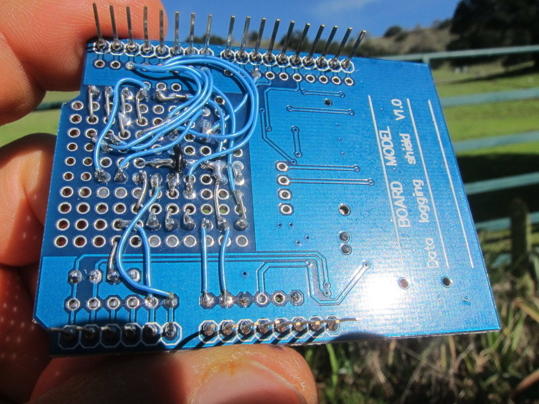
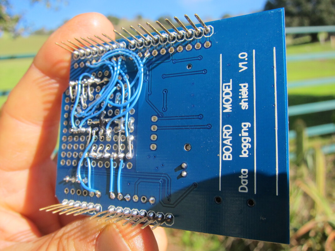
Perimeter pins weren't soldered at all. Soldering them wasn't easy either. I had to add flux to get the solder to flow.
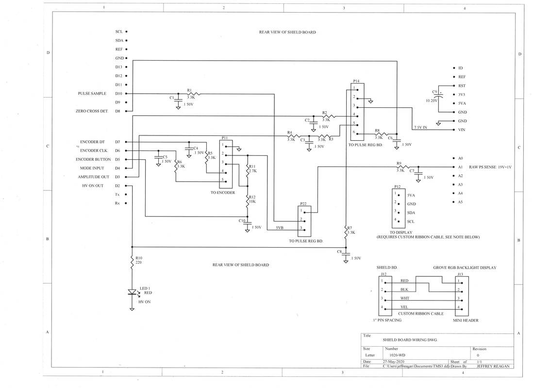
WIRING DIAGRAM PDF
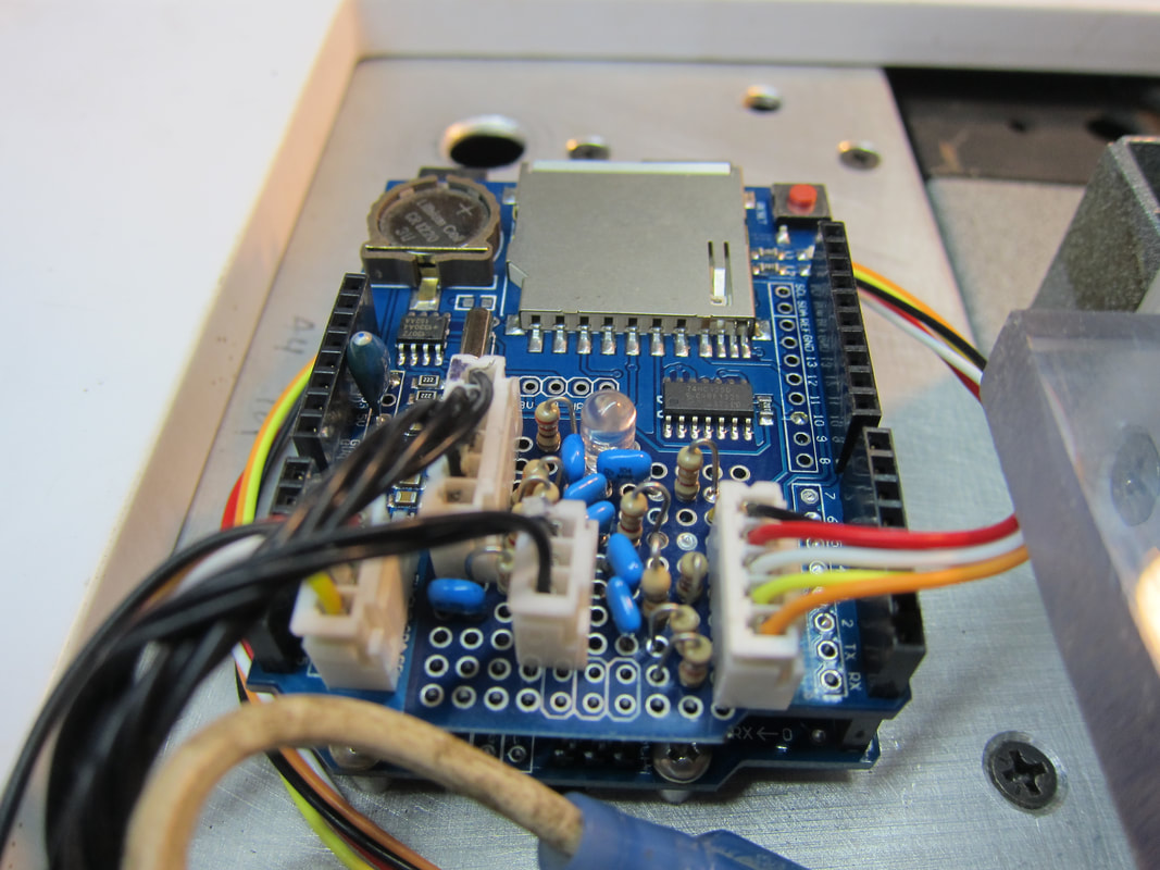
Parts List:
Data Logging Shield V1.0, 1EA.
LED1: LED RED 4MM, 1EA.
C1-C8: CAP .1uF 50V, 8EA.
C9: CAP 10uF 20V, 1EA.
C10: CAP 1uF 50V, 1EA.
R1-R9: 3.3k 1/4W, 9EA.
R10, RES 220 OHM 1/4W, 1EA.
R11: RES 2.7K 1/4W, 1EA.
R12: 10K 1/4W, 1EA.
P11: 5 PIN HEADER .1" PIN SPACING, 1EA.
P12: 4 PIN HEADER .1", 1EA.
P14: 6 PIN HEADER .1", 1EA.
P22: 3 PIN HEADER .1", 1EA
Note: Consider replacing all resistors with 3.3K 1/4W, all capacitors with .1uF 50V.
TMS Design
by
Jeffrey Philip Reagan
is licensed under a
Creative Commons Attribution-ShareAlike 4.0 International License
.
Home
Schematics, TMS #5
Applicator Coil, TMS #5
Test Data
Transcranial Magnetic Stimulator Design
System Schematic, SN #3
TMS REV C, Efficient Monophasic
Pulse Regulator Board
Arduino/Shield Board
Frequency Metering Board
Capacitor Bleeder/PRF Sense Divider Board
Switch Deck
Gate Drive/HV Rect./Reg. Divider Board
Applicator Coil
Small Control Panel
Power Control Module Wiring
Triac Driver Board
Pulse Driver Board
About Me