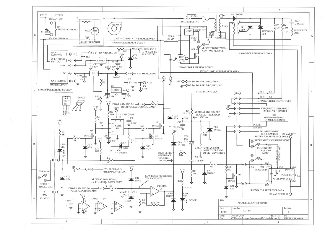
Pulse Regulator Board serves a few purposes. Small power supply regulators occupy some space. Noise filtering for computer inputs and outputs exists here. Pulse width modulation from the Arduino develops a 0-5 Volt DC reference voltage. An op-amp amplifies the 0-5 Volt output to be 0-24 Volts. This controls pulse amplitude. Excessive pulse frequency is limited here. An NE555 timer (U6) inhibits high voltage after the first pulse is applied in the setup mode. U6 maintains an inhibit, lasting for about six more seconds. Duration of the NE555-generated inhibit in the setup mode is unimportant, because the Arduino only applies primary power for 200 Milliseconds, then inhibiting reapplication of High Voltage for 15 seconds after the first pulse was applied. The NE555 detects application of a first applied pulse, then interrupting primary power, giving 8.7 Millisecond (half-line-cycle) interrupt speed. Pulse regulation is only achieved in the Setup and Normal modes.
In the Normal Mode this system functions like a giant relaxation oscillator. Voltage across the High Voltage Capacitor reaches a preset threshold, then an output pulse is initiated. Threshold voltage is set by the Arduino, which produces a Pulse Width Modulated output signal (giving 255 bit resolution). This signal enters the Pulse Regulator Board at JP14-4, which is filtered to produce a 0-5 Volt low level reference voltage. An Op Amp (U5) amplifies this to be a 0-24 Volt high level Reference Voltage. This biases the low end of a 32 Volt Diac, which triggers when the high end reaches threshold value, then discharging C12 into an Opto Isolator input on the Pulse Driver Board (External Trigger Input). Theoretical adjustable HV Capacitor voltage range is 1.2KV to 2.1KV with present component values. High voltage divider termination resistance determines the maximum voltage (R19+R20=58.7K at present).
GENERAL OVERVIEW--THIS DOES NOT CONSTITUTE A RECOMMENDED THERAPY--IT ONLY PROVIDES A THEORETICAL FRAMEWORK
Pulse regulation stability isn't perfect. In the Setup Mode, the primary Rheostat shall be adjusted in accordance with a provided LOOKUP TABLE, corresponding to the 0-255 bit readout on the Arduino display. The Arduino defaults to 100 when the Setup mode is initially selected (out of 255). The Rheostat should be set for minimum initially.
Finding Muscle Twitch Threshold: The applicator coil is placed just above one ear to stimulate the motor cortex. Pressing the Encoder button initiates a single shot. Stimulus is given while observing the opposite fingers to see if the muscles twitch. Two attempts are made, given a 15-second rest-time between attempts (the Arduino has a built in 15 second delay). Lacking any response, Amplitude is adjusted upwards, along with the the Rheostat setting. For each Amplitude setting, the Rheostat should be set accordingly. a stable operating range lies between upper and lower bounds shown on an accompanying graph (below the lookup table). Amplitude and Rheostat settings are incremented upwards until Muscle Twitch is observed for one out of every two applied pulses. This is referred to as 100% Muscle Twitch Threshold. FDA approved protocol for 100% Muscle Twitch Threshold is 4-seconds ON, 11 Seconds OFF.
I'm attempting to replicate equipment used for a recent National Institutes of Health (NIH) study; one which only applied stimulus to the Left Hemisphere. The Applicator Coil was first placed over the Left Motor Cortex: peak power was gradually increased until they identified Muscle Twitch Threshold. The Applicator Coil was then moved forward 2.5"-3" inches, placing it over the Left Dorsolateral Prefrontal Lobe. Another article suggests stimulus should always be applied to the DOMINANT Dorsolateral Prefrontal Lobe, which isn't necessarily located on the left side. Creating an excited state for the Non Dominant Prefrontal Lobe might actually cause harm. Further research is needed.
Getting back to the basics: first we determine Muscle Twitch Threshold. For therapy the Setup mode is then deselected. Amplitude setpoint is locked-in by the Arduino. Pressing the Encoder button again initiates Therapy: stimulus appears for 4-Seconds, followed by an 11-Second rest period; with the cycle repeating for 13 Minutes. Applied pulses are counted by a front panel mounted resettable Omron Event Counter. A log should be kept for how many applied pulses any individual receives. Seizures are seen in about .01% of patients that receive TMS. As such, Basic Life Support Certification is required for all TMS clinicians. We are warned: never treat Epileptics, or anyone with metal embedded into their skull.
The disadvantage of Relaxation Oscillator topology is; frequency gets determined by primary power source impedance. In the Regulated Pulse Mode, for any given Amplitude setting, the Rheostat can be adjusted to raise or lower applied Pulse Repetition Frequency (PRF). Resulting PRF appears in sync with the AC power line frequency. Anything below 10 Hz might appear depressing, and should probably be avoided. 15 Pulses Per Second is our target value, if we are attempting to replicate the recent National Institutes of Health (NIH) study. Meditative-state Brain Waves, or Alpha Brain Waves, range from 8-Pulses-Per-Second to 12 Pulses Per Second. Beta Brain Waves (15Hz) were applied in the recent NIH study.
In the Regulated Pulse Mode, the highest Rheostat setting can combine with the lowest Amplitude setting to produce a frenetic firing rate (excessive Pulse Repetition Frequency) which would go well beyond the ability of the High Voltage Power supply current rating. As such, Pulse Repetition Frequency limiting is provided. With initiation of each pulse, a 45 millisecond pulse inhibit is generated by the off-board Frequency Metering Board. This 45 millisecond pulse enters the board via JP21-4, which activates Q1, thus preventing further pulses from repeating within the 45 Millisecond inhibit period. Attempts to go beyond this PRF limit will produce a regulated frequency which reads about 22 Hz on the analog frequency meter: amplitude stability will be poor due to asynchronous operation (for not being well correlated with power-line frequency).
If Muscle Twitch Threshold cannot be achieved, other uses for this system may appear. Physical Therapists should find Nerve and Muscle Stimulus therapeutic for treating Charlie-Horse, Muscle Spasms, Muscle Knots, etc. For topical use the Max mode eliminates Pulse Regulation. The Amplitude setting is ignored. Available Pulse Repetition Frequencies are 10, 12, or 15 Pulses Per Second regardless of Rheostat settings, selectable by a rotary switch.
The Max Mode has an advantage in terms of Conducted Emissions radiated into the primary power line. No line filtering is provided in the present design. Induced line flicker is known to be brutal. But induced line noise should be worse in the Regulated Pulse Mode. In the Maximum Efficiency Mode, Primary SCR firing coincides with High Voltage Transformer Negative output polarity. The High Voltage Capacitor spends a couple milliseconds charged to substantial negative polarity, but this occurs while the transformer output is also negative: no current flows through the high voltage rectifier.
In the Regulated Pulse Mode, Primary SCR triggering appears as a direct result of rising High Voltage Capacitor voltage. This necessarily happens while the High Voltage Transformer output is Positive. The resonant relationship between the High Voltage Capacitor and the Applicator Coil drives capacitor polarity negative within 100 Microseconds, and that Negative polarity persist for about ~2 Milliseconds (until the Ringback SCR fires). Positive Transformer output cannot change High Voltage Capacitor polarity instantaneously, so the transformer secondary appears shorted for the ~2 Millisecond period. Fortunately Microwave Oven Transformers are Inductively Shunted; high Transformer source impedance is also desirable for Microwave Oven designers. High Transformer Impedance limits primary current, but not induced line noise. Conducted Emissions are probably atrocious for any case, but these should appear much more worse in the Regulated Pulse Mode.
SCHEMATIC PDF
Parts List:
U1: LM7824, 24V REG, 1 EA.
U2: LM7812, 12V REG, 1 EA.
U3: LM317, ADJ REG, 1 EA.
U4: LM7805, 5V REG, 1 EA.
U5: LM324, QUAD OP AMP, 1 EA.
U5X: IC SOCKET 14 PIN, 1EA.
U6: NE555, TIMER, 1 EA.
U6X: IC SOCKET 8 PIN, 1EA.
Q1-Q4: 2N7000, N FET 60V, 4 EA.
VZ1: DB3, 32V DIAC, 1 EA.
LED 1: LED YEL 4 MM, 1 EA.
LED 2: LED VIO 4 MM, 1 EA.
LED 3: LED RED 4 MM, 1 EA.
VZ2-VZ6: 6.2V ZENER, 5 EA.
CR1-CR7: 1N4007 DIODE 1KV 1A, 7 EA.
P8: CONNECTOR MOLEX 12 PIN MALE, 1EA.
J14: CONN HEADER 6 PIN .1" F, 1EA.
P21: CONN HEADER 6 PIN .1" M, 1EA.
J22: CONN HEADER 3 PIN .1" F, 1EA.
R1-R6, R23: RES 1K 1/4W, 7EA.
R7-R14: RES 10K 1/4W, 8EA.
R15: RES 120 OHM 1/4W, 1EA.
R16: RES 680 OHM 1/4W, 1EA.
R17: RES 2K 1/2W, 1EA.
R18: RES 39K 1/4W, 1EA.
R19: RES 56K 1/4W, 1EA.
R20: RES 2.7K 1/4W, 1EA. MAXIMUM VOLTAGE ADJUST
R21: RES 330 OHM 1/4W, 1EA.
R22: RES 560K 1/4W, 1EA.
C1-C8: CAP 1uF 50V, 8EA.
C9: CAP 220uF 50V, 1EA.
C10: CAP 10uF 25v, 1EA.
C11: 10uF 25v, 1EA.

TMS Design by Jeffrey Philip Reagan is licensed under a Creative Commons Attribution-ShareAlike 4.0 International License.
