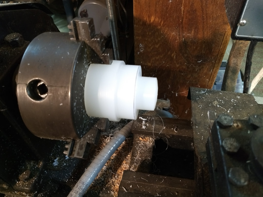
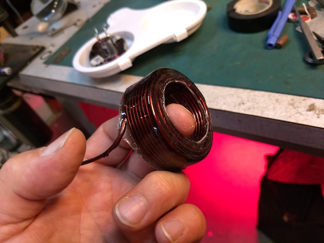
Mandrel in fabrication. Not shown here: the mandrel is slightly tapered to assist with coil ejection. Also, threaded 1/4"-20 holes allow three ejector screws to push dowel-pins forward toward the coil, which have rubber plugs in front of them, to cushion ejecting-force as it is applied to the coil. A hole is drilled into the face of the mandrel where the start winding is inserted. Teflon sleeving is applied to the start winding as it enters the mandrel, to keep it from getting glued into the hole. Some oil-based plumbers putty is also packed into the hole with the start winding, to discourage Epoxy from wicking into the hole with the start-lead.
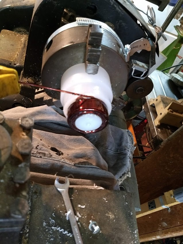
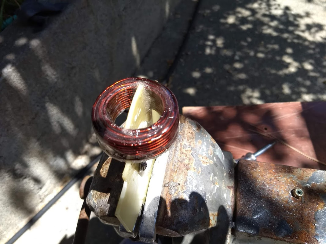
Here I'm "wet-winding" #12 HAPTZ magnet wire. I use paper-thin G-10 fiberglass between layers, sanded on both sides. 2-Ton Epoxy from Tap Plastics is applied liberally to both the fiberglass and wire. Adhesion isn't good to the fiberglass, but physical spacing is the desired effect. (I had an insulation breakdown failure in an early coil where magnet wires crossed physically.) The next revision will incorporate Nomex instead of fiberglass. Instead of Epoxy I will probably use Isolite 863 winding varnish, by Schenectady Manufacturing.
A layer of thin G-10 fiberglass is wound onto the mandrel prior to beginning winding. That is removed once the Epoxy is dry.
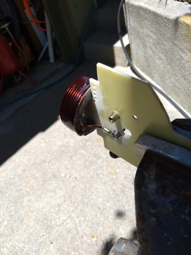
The mounting board is 1/8" G-10 fiberglass, sandblasted to roughen surfaces prior to application of Epoxy. Small holes are drilled next to the coil to increase joint integrity.
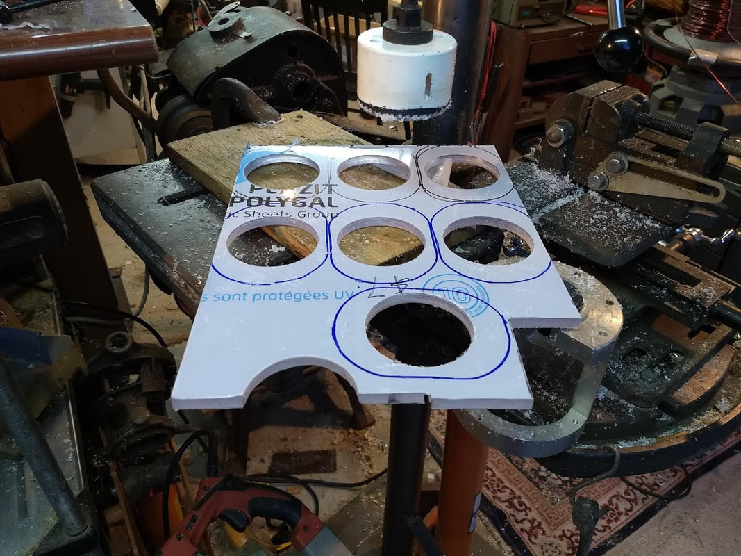
Adaptor plates are made of 3/8" inch Polycarbonate.
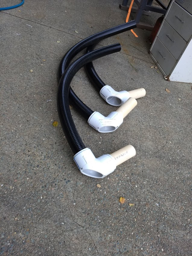
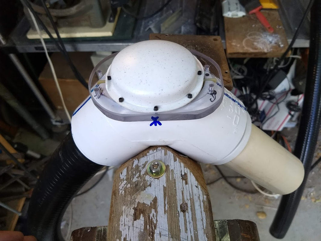
Elbows are cut on a table saw, then belt sanded flat. 2" hot-tub flexible PVC hose mates with the 2.5" PVC elbow via an adaptor, as does the 2" PVC exhaust duct. The long exhaust duct serves as both a handle and a finger guard. We don't want anyone touching high voltage inside the applicator coil assembly. A mesh-screen bonnet will eventually be attached, to keep foreign objects out of the exhaust port. I shall avoid restricting airflow.
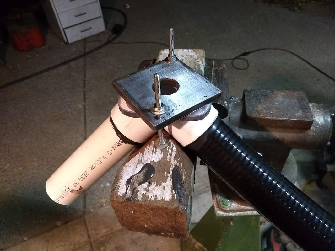
The thick metal plate seen here is a drill-bushing. The drill-bushing is clamped down onto the polycarbonate adaptor plate and PVC elbow, holding both tightly together prior to drilling tap-drill holes, for 6-32 thread size. Using a drill bushing assures all adaptor plates will be interchangeable.
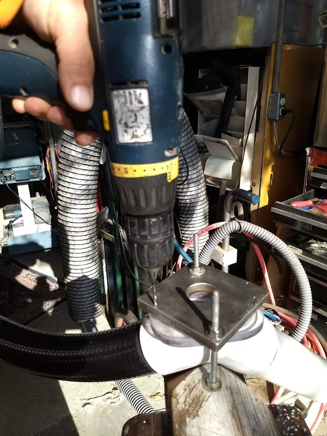
The drill-bushing plate is steel, pre-drilled using a 6-32 tap drill. Here we see a 6-32 tap drill plunging through the drill bushing, the adaptor plate, and the PVC elbow, which will be done in four locations. Next the Polycarbonate adaptor-plate gets redrilled with #6 through holes, and then countersunk from the top. Finally the elbow gets tapped with 6-32 threads in four places.
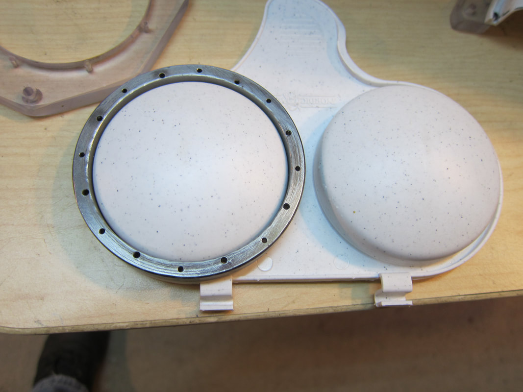
Here we see the Nordic Ware egg poacher fitted with another drill bushing. Only 8 of the 16 holes in the drill bushing are needed. (My first attempt located the holes too close to the egg poacher shell, and they were too big.) The ring of holes along the centerline of the steel ring are 2-56 machine-screw tap-drill hole size. I ignore the holes closer to the center of the ring. Again, using a drill bushing assures cover interchangeability.
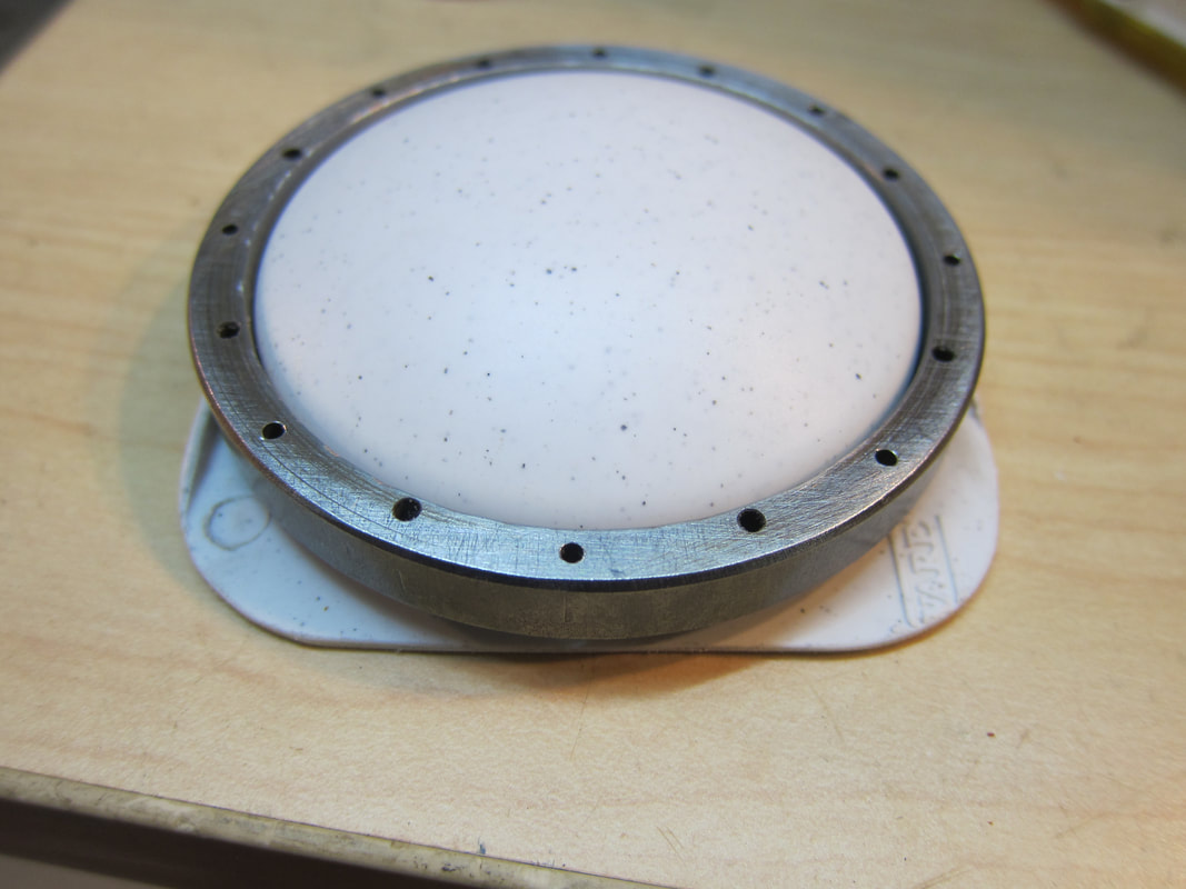
I carefully deburr the cut cover, so not to scratch the dome.
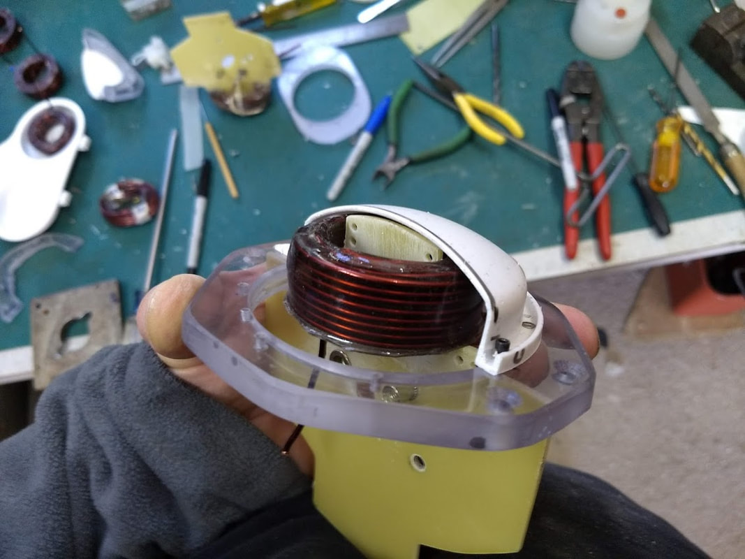
The coil-cover is Polypropylene: it comes from half of a Nordic Ware dual microwave egg poacher. I cut each egg-poacher into two covers. To assure proper coil alignment prior to gluing. I sawed this cover in half. Rotating the half-cover helps me locate the coil correctly before I apply mounting Epoxy. 2-56 socket-head-cap-screw heads fit neatly into the channel encircling the Nordic Ware egg poacher.
I anchor the coil wires to RivNut inserts, which are installed in the fiberglass mounting plate before I apply mounting Epoxy. I mix garden variety sand with the Epoxy to form rugged mounting material. Epoxy is good for binding surfaces together. It isn't structurally sound without sand-fill added to the mix.
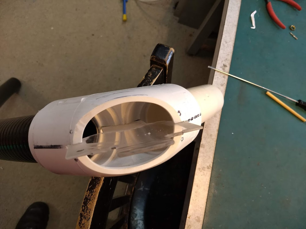
This template helps me locate slots properly, which is necessary for standardized coil mounting plates to install correctly. The slot in the back is cut before any PVC glue is applied. A stack of hack-saw blades gets stroked across through the inlet and outlet ports, thus cutting a thick slot across the inside corner of the elbow. The stack of blades is built-up to be the thickness of the coil mounting plate. Once the cut breaks through to the backside of the PVC elbow, blades are inserted through the front: a path is cleared for the butt end of coil mounting plate to slide in. The same stack of blades is drawn outward through the front port at black lines located along the center of the PVC, to clear guide-slots for each side of the coil mounting plate. Then the 2" inch I.D. to 2.5" inch O.D. PVC pipe adaptors are glued in. The stack of blades gets stroked through again, to clear interference posed by the adaptors.
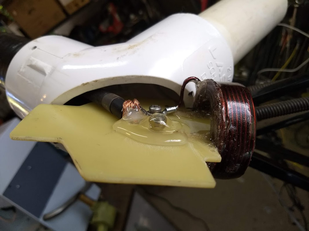
Hot Glue encapsulates the high voltage terminal, which is tied to the center lead of the coil, also known as the "start winding" within the coil. This puts outer-turns (the "finish winding") close to ground potential, to minimize shock hazard. #13 AWG (13 Gauge) RG-134 Coax brings pulse-current to the coil. A spring-steel cable clamp anchors the cable to the fiberglass coil mounting plate. The center conductor ports through a hole in the mounting plate to a terminal on the opposite side, which is also potted in hot glue. Hotspot winding temperature checked in at 199.6 degrees, using an Infrared thermometer. But airflow over the hot glue is brisk, so melting shouldn't occur.
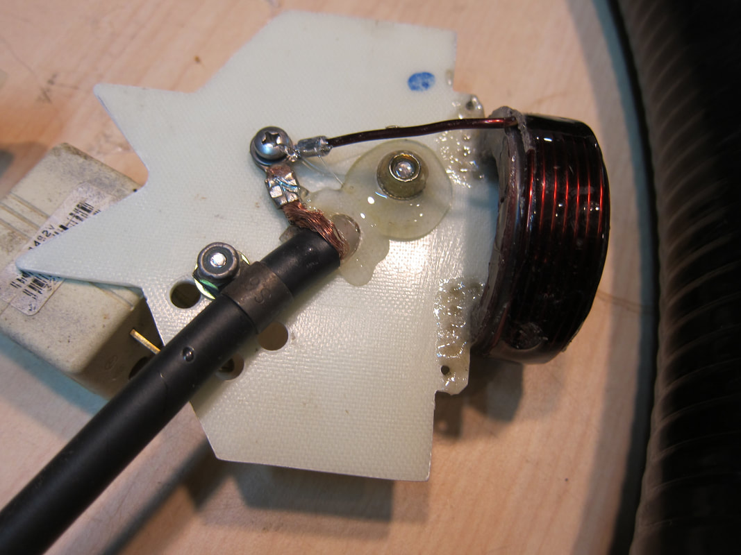
The butt-end is seen notched out here (so the coil mounting plate only comes flush with the crotch of the PVC elbow on the backside). The spring-steel cable clamp is also visible here. Hot glue provides a thick layer of insulation over energized hardware.
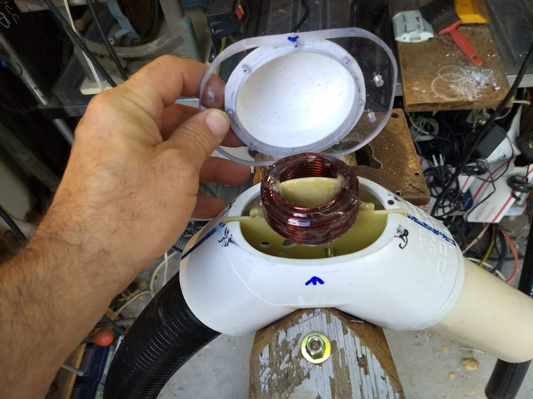
Cover placement is nearly complete.
Not shown here, a 6-32 allen set-screw threads into a hole from the side of the crotch on the PVC elbow. The allen screw impinges on the face of the fiberglass coil mounting plate, to keep it held in position. The coil mounting plate is an interference fit with the guide slot, so in/out sliding motion wouldn't be expected, even without a set screw.
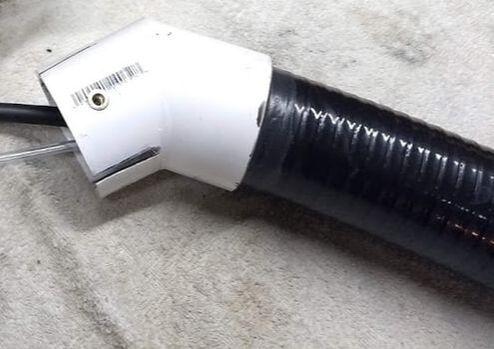
Flexible PVC pipe terminates to the blower box, which has a square exhaust port. RivNut inserts and slots adapted the round PVC to the square chassis port.

TMS Design by Jeffrey Philip Reagan is licensed under a Creative Commons Attribution-ShareAlike 4.0 International License.
