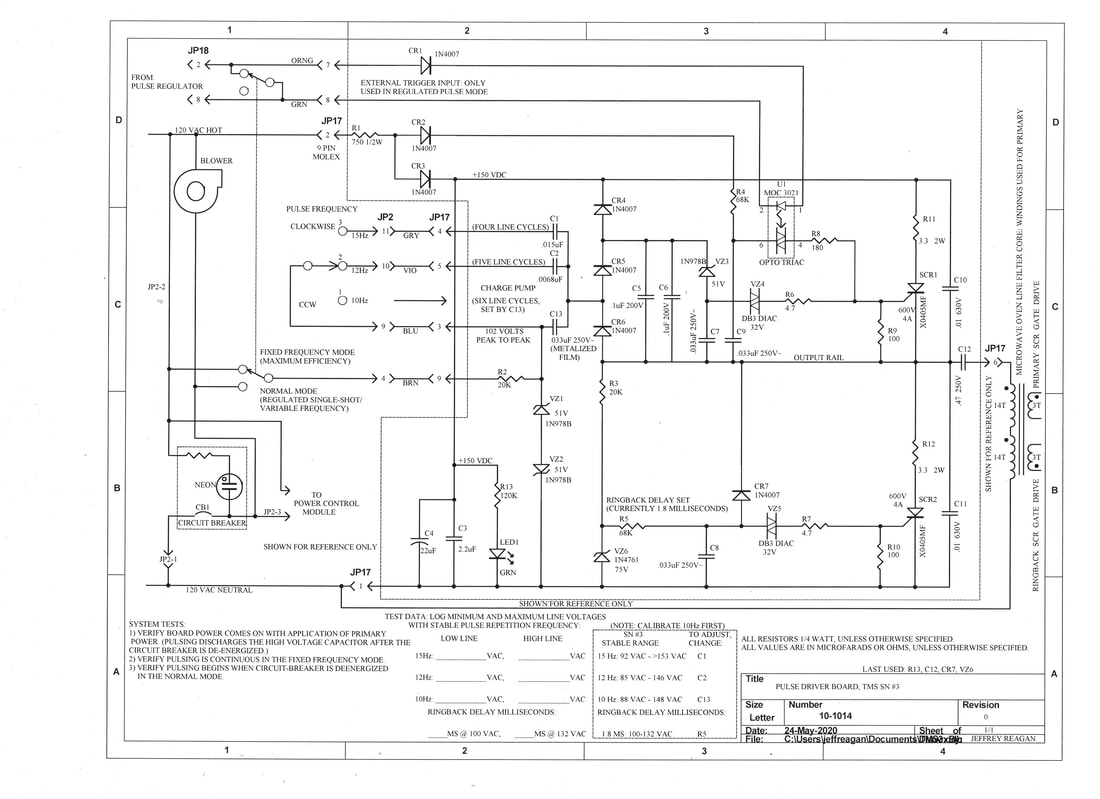
Theory of Operation: The pulse driver board produces push-pull capacitor-coupled output that drives a pulse transformer primary, with secondaries that alternately drive gates of two hockey-Puck SCRs, which in turn drive high voltage capacitor coupled surges through an applicator coil in a quasi-resonant fashion.
Board Power Supply: half-wave rectified ~130-Volts DC is drawn from the AC power line. 750 Ohm R1 limits peak charging current into Neutral-referenced-capacitors C3 and C4. Resistor R13 powers LED 1, giving a green indication whenever DC voltage is present.
Analog Line Frequency Divider: Whenever AC line voltage is applied to P17 Pin-9, it passes through 20K-Ohm-R2, developing clipped square-wave AC across Zeners VZ1 and VZ2 (102 Volts peak to peak). Transitions pump charge via capacitor C13 through diodes CR5 and CR6 to charge capacitor C5-C6, with Output capacitor C12 providing an AC return path. Voltage across C5-C6 rises in a stepwise fashion until Zener VZ3 and Diac VZ4 conduct, firing SCR1, which discharges C5-C6, thus restarting the sequence. This forms a primitive "divide-by-N counter, which is used here for counting power-line cycles. Provisions are made for divide-by-4 (15Hz), divide-by-5 (12Hz), and divide-by-6 (10Hz). Continuity provided between P17 pins 3 and 4 selects 15 Hz by placing capacitor C1 in parallel with C13. Continuity placed between P17 pins 3 and 5 selects 12 Hz by placing C2 in parallel with C13. Charge pumping through C13 alone produces 10 Hz.
Output Section: Rising voltage across capacitor C5-C6 surpasses 83 Volts (the sum of breakdown voltages presented by the 51 Volt zener and the 32 Volt Diac). Diac VZ4 fires, partially discharging capacitor C7 into the gate of thyristor SCR-1 (via R6). SCR-1 triggers, driving the output rail positive. Capacitors C5 and C6 are discharged via diode CR4 through thyristor SCR-1. Surge current from capacitor C4 drives an offboard pulse-transformer primary through .47 uF capacitor C12; a secondary winding triggers the Primary Output-Stage SCR, thus dumping the 20 uF Output-Capacitor's charge into Applicator-Coil inductance. Applicator Coil field peaks after 50 microseconds. Collapsing field pulls the HV Output-Capacitor polarity negative by resonant action.
Capacitor C12 quickly charges to 130 Volts: current through R3 develops 75 Volts across zener VZ6, so C8 begins charging via R5. C8 reaches about 32 Volts within a couple milliseconds, then Diac VZ5 fires via resistor R7, triggering thyristor SCR-2 to switch, thus dumping the 150 Volt charge stored in C12 through the pulse transformer primary, this time with reverse polarity. Capacitor C8 discharges via diodes CR7 and thyristor SCR2. The negative-going output pulse fires the "Ringback" high-voltage SCR: negative Output Capacitor charge is dumped back into the applicator coil. Reverse polarity field appears. Collapsing field "rings back" to leave the HV Output Capacitor charged positively again. Hence, pulse by pulse, energy in the output circuit is recycled.
High voltage transformer primary phasing effects efficiency differently in either of two modes. In the High Efficiency mode, charge-pumping should be set up to trigger the Primary high-voltage SCR while the high voltage transformer output is negative. This is prefered because the Primary high voltage SCR is poised to short-circuit positive transformer. This only happens when primary HV SCR triggering coincides with positive HV transformer output. (The high voltage transformer output is half-wave rectified.) In the driver board, charge pumping is also half wave rectified by nature. Charge pumping shall increase voltage in capacitors C5 and C6 on the opposite half cycle as when the high voltage transformer is increasing HV Output Capacitor voltage. This assures that we will trigger the Primary Output SCR while high voltage transformer output polarity is negative going.
In the High Efficiency Mode, Output Capacitor voltage discharges and reverses polarity while the high voltage transformer output is negative, thus no current flows through the high voltage rectifier. Two milliseconds later the Ringback SCR fires, returning capacitor polarity to positive before transformer output trends positive. In this way, we only trickle-charge the HV Output Capacitor positively, though it drives the applicator coil negatively, with the HV Output Capacitor remaining negatively charged for about two milliseconds after Primary SCR discharge was initiated. Firing repetition rate is fixed in the High Efficiency Mode, set for 15 Hz here.
In the Normal Mode, an off-board Pulse Amplitude Regulator initiates Primary Output SCR triggering. This happens when the HV Output Capacitor reaches a preset threshold Voltage. This necessarily requires firing the Primary Output SCR while Output Capacitor voltage is rising. Hence we do fire the Primary Output SCR directly across positive high voltage transformer output, which presents a temporary short circuit, which persists for a couple milliseconds. High voltage capacitor polarity reverses while high voltage transformer output remains positive. Thus peak primary line current will be quite high (44 Amps peak) for a couple milliseconds, until the Ringback Output SCR is triggered, returning HV Output Capacitor charge to the positive polarity. The high voltage transformer has high leakage inductance, thus limiting peak current driven into the negatively charged HV capacitor.
External triggering comes in on connector-P7 pins 7 and 8. In preparation for this, diode CR2 charges Capacitor C9 to +150 Volts via resistor R4. Positive polarity entering Pin-7 passes through diode CR1 to illuminate the Opto Triac input LED, with LED drive current returning through P-17 Pin-8. The opto Triac fires, discharging capacitor C9 into the gate of Thyristor SCR1, thus initiating a positive-going output pulse. Positive potential at the output initiates the next negative-going output pulse about two milliseconds later, as described above. Opto Triac U1 is given a half-cycle to reset back to an off state after each operation, by virtue of a half-wave rectifier charging capacitor C9. Resistor R8 limits the Opto Triac output peak current to a safe value. External triggering is shorted in the High Efficiency mode by contacts in the Normal/Max front panel toggle switch. The Normal/Max toggle switch has a locking detent at the midpoint, preventing accidental switching. (The bat-handle must be pulled out momentarily to change switch positions.)
Internal high voltage bleeder resistors won't discharge the output capacitor within one second, which is generally considered good practice, from a personnel safety standpoint. Incorporating a mechanical crowbar would present another set of problems. Firing the output SCRs alternately at 10 to 15 pulses per second (PPS) discharges stored energy satisfactorily within one second, but this requires primary power remain active until discharge is complete. In the High Efficiency Mode, 15 PPS Output-Stage SCR drive remains active whenever primary power is applied. In the Normal Mode, 15 PPS Output SCR drive activates when the front panel circuit breaker is de energized. (Line voltage is provided through the cooling fan motor.) A neon bulb powered by a bleeder resistor is meant to indicate lingering high voltage in the Output Capacitor. This neon bulb resembles a 3AG fuse, and can be seen from above the output capacitor, located on the bleeder board.
Technicians should exercise good judgement before servicing this unit. Neon bulbs fail. Use common sense. Disconnect line voltage. Short the capacitor with an insulated shorting stick to assure full discharge before making physical contact with any internal circuitry. Never work on high voltage alone.
Parts List:
SCR1, SCR2: X0405MF, 4A 600V SCR, 2ea.
CR1-CR7: 1N4007, 1KV 1A (Any diode would do, rated in excess of 400 Volts Peak Inverse Voltage), 7 ea.
VZ1-VZ3: 1N978, 51 Volt Zener, 3 ea.
VZ4, VZ5: DB3, 32 Volt Diac, 2 ea.
VZ6: 1N4761, 75 Volt Zener, 1 ea.
LED 1: Green LED, 1 ea.
U1: MOC3021, 400 Volt Opto Triac, 1 ea.
R1: 750 Ohm 1/2W, 1 ea.
R2, R3: 20K 1/4W, 2 ea.
R4, R5: 68K 1/4W, 2 ea.
R6, R7: 4.7 Ohm 1/4W, 2 ea.
R8: 180 Ohm 1/4W, 1 ea.
R9, R10: 100 Ohm 1/4W, 2 ea.
R11, R12: 3.3 Ohm 2W Metal Film (or 1W Carbon Composition), 2 ea.
R13: 120K 1/4W, 1 ea.
C1: .015uF 200V X7R, 1 ea.
C2: .0068 200V X7R, 1 ea.
C3: 2.2uF 250V Metalized Film, 1 ea.
C4: 22uF 160V Electrolytic, 1 ea.
C5, C6: .1uF 200V Metalized Film, 2 ea.
C7-C9, C13: .033uF 250V~, 3 ea.
C10, C11: .01uF 630V Ceramic, 2 ea.
C12: .47uF 250V Metalized Film, 1 ea.
P1: Molex 03-09-2092, 9-Pin .093" Pin Male, 1 ea.
Fiberglass Circuit Board Material, 1/16" thick, perforated with .1" spacing, as needed.
|
|

TMS Design by Jeffrey Philip Reagan is licensed under a Creative Commons Attribution-ShareAlike 4.0 International License.
