Theory of Operation:
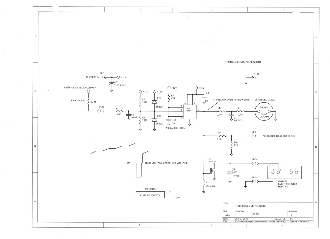
Signal Input enters at connector P-20, which consists of current proportional to HV Output Capacitor Voltage. HV Output Capacitor Voltage peaks at a maximum of about 2.2KV, followed by a maximum negative excursion of -1.9KV. An external 2.2 Megohm high voltage resistor sources plus 1 milliamp and minus .86 milliamps, entering this board through P-20, thus passing through resistor R1 to the junction of resistors R2 and R3, a point which is biased to 6 Volts DC by Voltage division of R2 and R3. Capacitor C1 filters out noise. Diodes CR1 and CR2 protect the Trigger input of One-Shot Timer U1 from transient over Voltage conditions. One-Shot timer circuit input impedance is set for 4.55K (the parallel value of R2 and R3). Input triggering range showed full functionality down to 50% of normal input line voltage.
+1 milliamp input current adds 4.55 Volts to the existing 6 Volt input equilibrium, for a 10.55 Volt maximum positive excursion seen at the trigger input of U1 (pin-2). This doesn't have any real effect, as the trigger input is activated by a low-going transition (dipping below 1/3 of the supply voltage, or below 4 Volts in this case). When the Primary high voltage SCR triggers, voltage at the positive terminal of the high voltage Output Capacitor goes to zero for about 100 microseconds. Then collapsing magnetic field drives the HV Output Capacitor Voltage negative, to about -1.9KV. At this point -.86 milliamps enters the signal input via J-20, pulling the One-Shot's Trigger Input 3.9 Volts below the 6 Volt equilibrium, or down to 2.1 Volts with respect to board ground. This falls below the trigger threshold at pin-2, triggering the One-Shot timer output to go high for a period determined by the time-constant of resistor R4 and Capacitor C2. This calculates to be 42 milliseconds. Testing revealed a 45 millisecond period actually resulted.
Hence, 100 microseconds after each firing of the primary high voltage SCR, we get a 45 millisecond 10.5 Volt output pulse from One-Shot timer U1, measurable at output pin 3. Resistor R11 loads this output, assuring the output voltage will be consistent. This One-Shot timer output serves various purposes, all relating to pulse repetition rate. (Not all of the outputs are used in the present design.)
Frequency to Voltage conversion is done by taking the average value of One-Shot timer (U1 Pin-3) output over time. Arduino Analog Input A0 receives an input filtered in this manner (but this signal is not used by program code in the present design). One-Shot output pulse voltage (seen at U1 pin-3) passes through Resistor R5 and is divided down by R6. Capacitor C5 filters repetitive 45 millisecond pulses to produce a "DC" value (with the pulse repetition frequency causing minor ripple). Calculated output voltage is 1.05 Volts @ 30 Hertz, which exits the board at pin 1 of connector J21, connecting to Arduino Analog Input A0.
Resistors R7 and R8 drive a 25 microamp-full-scale analog meter, mounted on the front panel. Capacitor C4 smoothes out the pulse component. The result is a 1:1 reading, with 25 microamps representing 25 Hertz pulse repetition rate. 15 microamps represents 15 hertz, our desired pulse repetition frequency. Meter movement tracks frequency linearly.
Resistors R9 and R10 divide down the 10.5 Volt One-Shot output to 5V TTL level, which exits the board at connector J21 pin-4. This TTL output is compatible with the Arduino Digital input port, D10, where it is applied. (This Arduino input port is not presently used by the existing program code.) But this TTL signal passes through the Pulse Regulator Board where it is used, to limit maximum pulse repetition rate. Any TTL High state originating here turns on a field-effect transistor on that board, which is poised to short out trigger pulses destined for the Pulse Driver Board. Thus retriggering of the output stage cannot occur while One-Shot timer U1's output is high. Extending One-Shot timer U1's pulse-width reduces maximum possible operating frequency. Maximum possible operating frequency is limited to below 25 pulses per second with the present One-Shot pulse width setting.
Field effect transistor Q1 switches ON whenever One-Shot timer U1's output is high. Zener VZ1 protects Q1 from transient over-voltage conditions. Electrical continuity appears at connector P24, between pins 1 and 2, whenever One-Shot timer U1's output is high. Off-board front panel mounted Event Counter (Omron brand, Model: H7EC-NV) counts pulses, and is push-button resettable.
SCHEMATIC PDF
Parts List:
R1: 10K 1/4W, 1 ea.
R2, R3: 9.1K 1/4W, 2 ea.
R4: 42K, 1 ea.
R5: 330K 1/4W, 1 ea.
R6: 33K 1/4W, 1 ea.
R7, R8: 220K 1/4W, 2 ea.
R9: 5.6K 1/4W, 1 ea.
R10: 4.7K 1/4W, 1 ea.
R11: 470 Ohms 1/2W, 1 ea.
VZ1: 6.2 Volt Zener, 1N753, 1 ea.
CR1, CR2: 1N4007 Diode, 1KV 1A, 2 ea.
C1: Capacitor 100pF 100V, 1 ea.
C2: 1uF 100V Metalized Film or NPO, 1 ea.
C3, C4: 1uF 50V, 2 ea.
C5: 10uF 20V Tantalum, 1 ea.
C6: 100uF 20V Tantalum, 1 ea.
Q1: 2N7000 N-FET, 1 ea.
U1: NE555 Timer, 1 ea.
UX1: 8-pin Dip Socket, 1 ea.
P20: 2-Pin Male Header, Large, 1 ea.
J21: 6-Pin Female Header, .1" Pin Spacing, 1 ea.
JX21: Female Pin, 6 ea.
P24: 2-Pin Header, make, .1" pin Spacing, 1 ea.
Meter Lugs: 1/4" hole size, 2 ea.
Board, perforated 1/16" thick G10 or FR4 .1" hole spacing, as needed.

TMS Design by Jeffrey Philip Reagan is licensed under a Creative Commons Attribution-ShareAlike 4.0 International License.
